
Blog

How to Choose the Right Temperature Sensor?

Choosing a temperature sensor is not just a matter of matching a probe to a temperature range. The right choice depends on accuracy, response time, installation conditions, and the cost of measurement errors. A sensor that performs well in a dry laboratory may drift or fail beside a vibrating pump, inside a washdown line, or under repeated thermal cycling. Small details matter.

Technical references help turn those details into practical decisions. IEC 60751 specifies characteristics for industrial platinum resistance thermometers, while IEC 60584 covers thermocouples. NIST guidance on measurement uncertainty also shows why a sensor’s stated accuracy is only part of the picture: calibration, wiring, readout equipment, and operating conditions can all affect the final result. These sources provide a sound starting point, but they cannot replace testing in the actual process.

Temperature Sensors should therefore be compared against the demands of the application, not selected by price or range alone. Consider a food-processing pipe that needs stable readings during cleaning, or a furnace where a fast response matters more than fine resolution. The best fit may be an RTD, thermocouple, thermistor, or another technology. There is no universal winner. And specifications can look reassuring. Real installations are less tidy. A careful selection process should weigh sensor construction, calibration needs, response time, environmental protection, and the consequences of a faulty reading—then leave room to review assumptions before purchase.
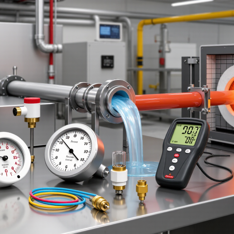
How to Choose the Right Temperature Sensor?

Define the Measurement Task and Required Temperature Range

Before selecting a temperature sensor, define what the measurement must reveal. Are you monitoring a slowly changing room, a hot pipe, or a brief process spike? Note the medium, contact method, response time, installation depth, and expected temperature extremes. A sensor suitable for air may lag when pressed against a thick metal surface. Small details matter.

Set the operating range with room for start-up, shutdown, cleaning, and faults—not just the normal setpoint. NIST’s ITS-90 temperature scale extends from 0.65 K to 1,357.77 K, but that reference scale does not mean every sensor works across it. Check the sensor’s own rated range and calibration conditions. ASTM E230/E230M lists Type K thermocouple standard tolerance as ±2.2°C or ±0.75% of temperature, whichever is greater, over its specified range. That error can be significant in a tight control loop. It is easy to overlook. Recheck the allowance against your process limits.

Tips: Write down the minimum, maximum, accuracy target, and response time before comparing sensor types. Include the expected measurement error from the sensor, wiring, and readout. If the range is based on one old reading, question it; a short data-logging trial may reveal overlooked spikes.

Compare Common Temperature Sensor Technologies

Temperature sensors differ in range, response time, accuracy, and installation needs. Thermocouples tolerate very high temperatures and respond quickly, making them useful near furnaces or hot pipes. Their readings can drift, so calibration and suitable wiring matter. Resistance temperature detectors, or RTDs, often provide stable, repeatable measurements across moderate ranges. They may respond more slowly and cost more than simpler options. Thermistors are sensitive and compact, which suits tightly controlled spaces such as equipment enclosures. Their useful temperature range is usually narrower. No option wins everywhere.

Infrared sensors measure surface temperature without touching the object. They help when a target moves or is difficult to reach, but steam, dust, shiny metal, and viewing angle can affect readings. Check the expected temperature range, required accuracy, response time, and sensor placement before comparing specifications. Also consider the full measurement setup: a probe, cable, mounting point, and reader can each introduce errors. A sensor tested in one location may behave differently after installation; that detail is easy to underestimate.

Tips: Match the sensor to the actual material and operating conditions. Test it at the intended distance or mounting depth, then compare readings with a trusted reference. Keep a simple record of calibration dates and unusual readings. A small trial can reveal assumptions you missed.

How to Choose the Right Temperature Sensor? - Compare Common Temperature Sensor Technologies

Technology How It Works Typical Temperature Range Typical Accuracy Response and Practical Strengths Limitations and Common Uses
Thermocouple Two dissimilar metal conductors generate a small voltage that varies with the temperature difference between the measuring and reference junctions. About −200°C to 1,250°C for commonly used Type K sensors; limits depend on thermocouple type, probe construction, and environment. Often around ±1–2°C or ±0.75% of the measured temperature for standard-grade sensors; the applicable tolerance depends on type and temperature. Wide operating range, rugged construction, and fast response with a small exposed junction. Self-powered sensing element. Requires cold-junction compensation and suitable signal conditioning. Accuracy and long-term stability are generally lower than a good RTD. Common in furnaces, engines, and industrial processes.
RTD (Resistance Temperature Detector) Measures the predictable change in electrical resistance of a metal element, most commonly platinum. Approximately −200°C to 600°C for many industrial platinum RTDs; specific designs may have different limits. Platinum RTD tolerance classes commonly range from about ±0.15°C to ±0.5°C near 0°C; tolerance changes with temperature and sensor class. Good accuracy, repeatability, and long-term stability. Suitable for precise measurements over a broad moderate-temperature range. Usually costs more and may respond more slowly than a small thermocouple. Needs excitation and resistance-measurement circuitry. Common in laboratories, process control, and HVAC systems.
Thermistor Measures the substantial, nonlinear change in resistance of a temperature-sensitive semiconductor material. Typically about −50°C to 150°C, depending on the thermistor and its packaging. Often about ±0.1°C to ±1°C over a specified, calibrated range; accuracy depends on calibration and measurement circuitry. High sensitivity and small size can provide fast response and good accuracy over a limited temperature span. Nonlinear response and a narrower operating range than many RTDs or thermocouples. Self-heating can affect readings. Common in medical devices, battery packs, and temperature compensation.
Semiconductor temperature sensor Uses temperature-dependent electrical behavior in an integrated semiconductor circuit to provide an analog voltage, current, or digital reading. Commonly about −55°C to 150°C, subject to the device rating and operating conditions. Often around ±0.1°C to ±2°C, depending on the device, calibrated range, and specified conditions. Easy to interface with electronics; digital versions can simplify wiring and signal conversion. Well suited to compact, low-to-moderate-temperature applications. Generally unsuitable for very high temperatures or harsh environments. Some devices need close thermal contact and careful placement. Common in circuit boards, consumer electronics, and equipment monitoring.
Infrared (IR) sensor Estimates an object's surface temperature by detecting emitted infrared radiation without touching the target. Instrument-dependent; handheld and fixed units commonly cover ranges from below 0°C to several hundred degrees Celsius, with some models extending beyond 1,000°C. Often specified as approximately ±1–2°C or ±1–2% of the reading, depending on the instrument and measurement conditions. Non-contact measurement supports moving, inaccessible, or very hot targets. Response is often very fast. Measures surface temperature, not internal temperature. Results depend on emissivity, field of view, distance, and obstructions such as steam or dust. Common in moving-line inspection and hot or hazardous environments.

Selection note: Ranges, accuracy, and response time vary by sensor design, probe construction, calibration, installation, and measurement conditions. Check the specifications for the exact sensor and application before selecting a device.

Match Accuracy, Response Time, and Installation Requirements

How to Choose the Right Temperature Sensor?
Match Accuracy, Response Time, and Installation Requirements

Choosing a temperature sensor starts with the measurement, not the catalog. Decide how accurate the reading must be and across what temperature range. A process that tolerates a one-degree variation may not need the same sensor as a laboratory test. Also consider response time. A sensor inside a thick metal probe may react more slowly than one with a small exposed tip. That delay can matter when temperatures change quickly.

Installation affects readings, too. Check the available space, mounting method, vibration, moisture, and contact with the measured surface. A poorly placed sensor can report the temperature of nearby air instead of the pipe or material you care about. Small details matter. Not always obvious. Leave room for wiring and safe maintenance, and confirm the sensor’s materials suit the environment.

Tips: Compare accuracy across the full operating range, not just at room temperature. Check response time in the actual mounting setup. Keep the sensing tip firmly in contact with the target, and avoid placing it near heat sources that do not represent the process. If readings seem inconsistent, installation may be the issue; it is worth checking before replacing the sensor.

Assess Environmental Conditions and System Compatibility

Choosing the right temperature sensor starts with the conditions around it, not just its advertised range. Check minimum and maximum temperatures, moisture, vibration, pressure, and contact with oils or cleaning fluids. A sensor placed near a hot pipe may read differently from one immersed in moving liquid. Installation matters. A protective sheath can resist corrosion, but it may also slow response.

Match the sensor’s output and wiring to the controller or measurement system. ASTM E230/E230M specifies a standard tolerance for Type K thermocouples of ±2.2°C or ±0.75% of reading, whichever is greater, across its specified 0–1250°C range. That is a useful benchmark, not a guarantee of installed accuracy. Long leads, poor connections, and electrical noise can add error. I would also check calibration and replacement requirements; these details are easy to overlook.

Tips: Confirm the sensor’s wetted materials suit the process. Check connector type, cable length, and input range before ordering. If response time matters, test the sensor in its actual mounting arrangement. A datasheet alone can’t reveal every installation problem. That deserves a second look.

Verify Sensor Performance and Maintenance Needs

How to Choose the Right Temperature Sensor?

Verify Sensor Performance and Maintenance Needs

A sensor’s stated accuracy is only part of its real-world performance. IEC 60751 specifies Class A platinum resistance thermometer tolerance as ±(0.15 + 0.002|t|) °C. At 100 °C, that equals ±0.35 °C for the sensing element. It does not include errors from wiring, installation, or the measuring instrument. That matters. Check the complete measurement loop against a traceable reference, especially after installation or repair. IEC 60584-1 also defines thermocouple tolerance classes; compare the specified class with the process range and your acceptable error.

Maintenance should reflect actual operating conditions, not just a calendar reminder. Thermal cycling, vibration, moisture, and chemical exposure can accelerate drift or damage a probe. Keep records of calibration results, sensor location, and process conditions; trends can reveal gradual drift before readings become unreliable. Inspect cable jackets, terminal connections, and protective wells for cracks, corrosion, or looseness. A useful check is to compare the installed reading with a calibrated reference at representative operating temperatures. Check the whole loop. Set recalibration intervals using historical results and the risk of a bad reading. There is no universally correct interval, and extending one without evidence is a weak assumption. Use the IEC tolerance as a specification baseline, not a promise of field accuracy.

Go to Top